Contents

Arduino Due vs. embedded C - ARM reversing

  • arduino-cli: Command Line Interface for Arduino
  • ARM cross compiler: sudo apt install gcc-arm-none-eabi

Sample program
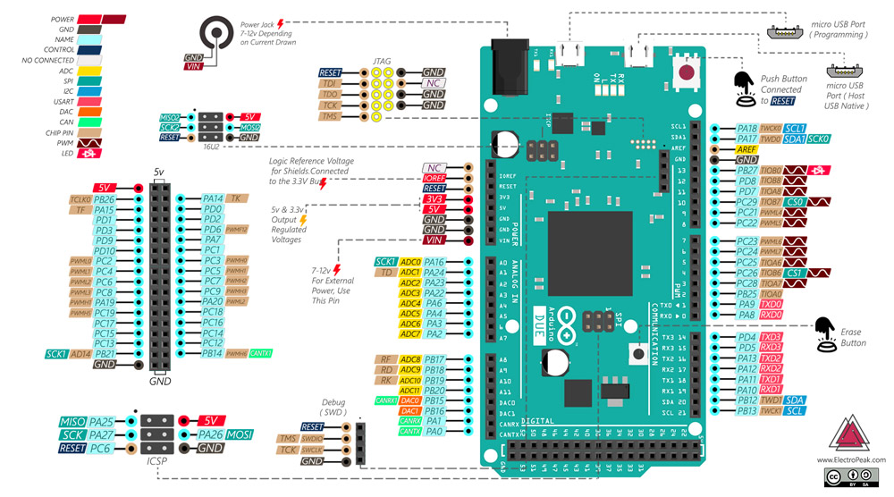
../img/arduino-due.jpg

We want to create the most simple program which goal is to light on the built-in LED, located at port PB27 on the Arduino Due.

Arduino

1
2
3
4
5
6
7
8
void setup()
{
    pinMode(LED_BUILTIN, OUTPUT);
}
void loop()
{
	digitalWrite(LED_BUILTIN, HIGH);
}

Embedded C

1
2
3
4
5
6
7
int main()
{
    PIOB->PIO_PER = 1<<27;       /* Enable port PB27 */
    PIOB->PIO_OER = 1<<27;       /* Configure PB27 as output */
    PIOB->PIO_ODSR = 0xFFFFFFFF; /* Write 1 in all PORTB ports */
    return 0;
}

Codes and compilation

1
2
3
4
5
6
7
8
9
$ ls -lR
./led-arduino:
total 4
-rw-r--r-- 1 pascal pascal 104 mai    1 12:58 led-arduino.ino
./led-embedded:
total 4
-rw-r--r-- 1 pascal pascal 81 mai    1 13:00 led-embedded.ino
$ arduino-cli compile --fqbn arduino:sam:arduino_due_x --output-dir led-arduino led-arduino
$ arduino-cli compile --fqbn arduino:sam:arduino_due_x --output-dir led-embedded led-embedded

Binary comparison

Arduino Embedded C
Storage use 10660 bytes 2544 bytes

The embedded C code is 5 times smaller than the Arduino one which is a bit “weird” as both codes do the same thing! Let’s find why by reversing binaries and analyzing assembly codes.

arduino-cli produces the *.elf binary and the *.hex file which is just a series of bytes to be loaded in the Arduino.

Reversing binaries

1
2
$ arm-none-eabi-objdump -S led-arduino/led-arduino.ino.elf > led-arduino.asm
$ arm-none-eabi-objdump -S led-embedded/led-embedded.ino.elf > led-embedded.asm

Arduino binary

 1
 2
 3
 4
 5
 6
 7
 8
 9
10
11
12
13
14
15
16
17
18
19
void init( void )
{
   80194:	e92d 41f0 	stmdb	sp!, {r4, r5, r6, r7, r8, lr}
  SystemInit();

  // Set Systick to 1ms interval, common to all SAM3 variants
  if (SysTick_Config(SystemCoreClock / 1000))
   80198:	4d3f      	ldr	r5, [pc, #252]	; (80298 <init+0x104>)
  SystemInit();
   8019a:	f000 f9f1 	bl	80580 <SystemInit>
  if (SysTick_Config(SystemCoreClock / 1000))
   8019e:	682b      	ldr	r3, [r5, #0]
   801a0:	f44f 727a 	mov.w	r2, #1000	; 0x3e8
   801a4:	fbb3 f3f2 	udiv	r3, r3, r2
 */
static __INLINE uint32_t SysTick_Config(uint32_t ticks)
{
  if (ticks > SysTick_LOAD_RELOAD_Msk)  return (1);            /* Reload value impossible */
[...]

Here is a part of the Arduino objdump. The assembly code is really long for such a program… It is easy to understand when we look at the source code of pinMode() and digitalWrite() (https://github.com/arduino/ArduinoCore-sam/blob/master/cores/arduino/wiring_digital.c). It does not only write a value into a register…

Embedded C binary

 1
 2
 3
 4
 5
 6
 7
 8
 9
10
11
12
13
14
61 00080148 <main>:
62 int main()
63 {
64     PIOB->PIO_PER = 1<<27;
65    80148:	4b04      	ldr	r3, [pc, #16]	; (8015c <main+0x14>)
66    8014a:	f04f 6200 	mov.w	r2, #134217728	; 0x8000000
67    8014e:	601a      	str	r2, [r3, #0]
68     PIOB->PIO_OER = 1<<27;
69    80150:	611a      	str	r2, [r3, #16]
70     PIOB->PIO_ODSR = 0xFFFFFFFF;
71    80152:	f04f 32ff 	mov.w	r2, #4294967295	; 0xffffffff
72    80156:	639a      	str	r2, [r3, #56]	; 0x38
73     return 0;
74 }

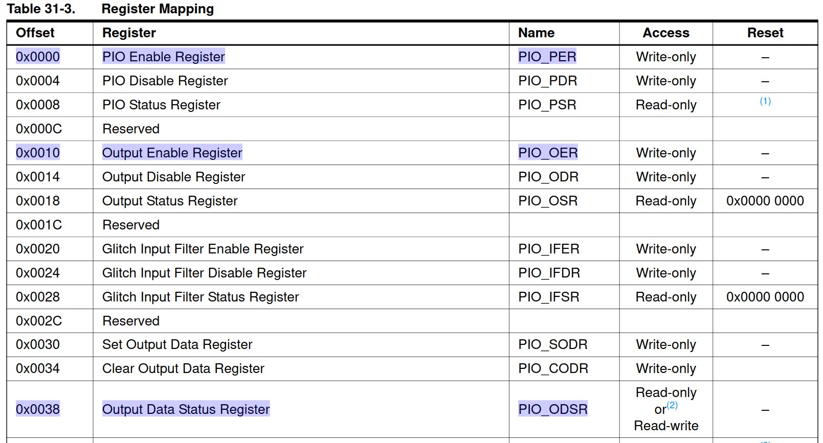
../img/mapping-sam3x.jpg

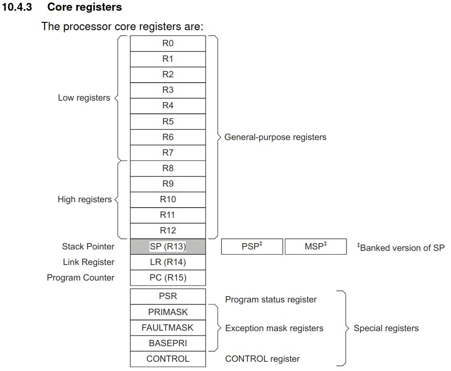
At first sight, it’s clearly easier. Step-by-step instruction decoding using mainly [2] and [6]:

  • mov.w r2, #134217728. Move the immediate value 134217728 in r2, a general purpose register. 134217728 = 0x8000000 (hex) = 0b1000000000000000000000000000 (bin) which is 1 on the 27th bit ! 😉
  • str r2, [r3, #0]. Store the value of r2 in r3, another general purpose register, with offset=0. According to the register mapping: PIO_PER is at the offset 0x0000.
  • str r2, [r3, #16]. Store the value of r2 in r3 with offset=16 (or 0x10 in hexadecimal). According to the register mapping: PIO_OER is at the offset 0x0010.
  • mov.w r2, #4294967295. Move the immediate value 4294967295 in register 2. 4294967295 = 0xFFFFFFFF (hex). In this case, we put all bits to 1. It doesn’t really matter as only the 27th has been enabled 😉
  • str r2, [r3, #56]. Store the value of r2 in r3 with offset=56 (or 0x38 in hexadecimal). According to the register mapping: PIO_ODSR is at the offset 0x0038.

../img/registers-sam3x.jpg

Conclusion

Embedded C code is usually quicker and smaller as long as we make some effort to study the datasheet. But it’s worth it when we’re working with embedded systems! 😉

References

  1. Cortex-M3 Revision r2p0Technical Reference Manual
  2. SAM3X datasheet
  3. ARMv7-M ArchitectureReference Manual
  4. A simplified ISA document
  5. Cortex-M3 TRM
  6. ARM assembly basics